
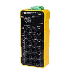
Grace Engineered GraceSense Hot Spot Monitor
Find faults before they find you with the GraceSense Hot Spot Monitor
The NFPA 70B, Chapter 17.9 Loose Connection states:
“Excessive heat in a circuit breaker can cause a malfunction in the form of nuisance tripping and possibly an eventual failure. Loose connections are the most common cause of excessive heat. Periodic maintenance checks should involve checking for loose connections or evidence of overheating…”
Safety by Design
- Better Maintenance Planning: Continuous temperature monitoring of electrical equipment identifies electrical hot spots before failures and expensive shutdowns occur.
- Simple Field Installation: Non-conductive fiber probes securely piggy-back onto existing bolted connections and potential heat sources. Heat sources include busbars, breaker connections, bus ducts, transformers, or any other potential hot spots.
- Any Voltage: Non-conductive technology safely applied to any electrical systems.
- Reduced Risk: Ability to monitor and retrieve temperature data of critical inaccessible connections and their associated alarms safely via GraceSense™ Web Utility Interface, Ethernet I/P, and MODBUS communication.
Operation
GraceSense™ Hot Spot Monitor is a non-conductive temperature monitoring and alarm device that identifies potential hot spots. This enables the user to predict failures in electrical equipment. Identifying faults before they occur allows you to avoid unplanned outages, service interruptions, and equipment failure. Therefore saving you precious time and money.
The Hot Spot Monitor has design and communication flexibility allowing it to be used as either a stand-alone option or as a fully integrated plant wide information system. Make plant wide integration simple when you connect the device via MODBUS TCP I/P or Ethernet I/P to the facility’s SCADA/ DCS systems. Furthermore, you can make stand-alone applications possible with GraceSense™ web interface to configure temperature thresholds, monitoring intervals, and relay outputs.
Installation
Mount the Hot Spot Monitor module on DIN rail inside the low voltage or control compartment. Securely attach the fiber temperature probe to the ring-style connector. Then, mount the probe assembly to existing bolted connections inside of the electrical equipment. Mount where heat sources (busbars, lug connections, etc.) or hot spots often originate. Once the bolted connection is made, route the other end of the fiber through the equipment and attach to the Hot spot Monitor module inside the low voltage compartment.
Applications
Current flowing through electrical connections is the main cause for electrical hot spots. These connections include lugs, screw terminals, circuit breaker stabs, busbar joints, etc. Furthermore, some critical hot spots are inaccessible by infrared thermography, and therefore, go unnoticed. The integrity of electrical equipment can be compromised when the internal bolted connections are subjected to wide load fluctuations or high harmonics.
- Low voltage/medium voltage switchgear
- Low voltage/medium voltage MCCs and Drives
- Motors, generators and dry-type transformers
- Load break & Transfer switches
- Bus ducts & busbars connections
- DC switchgear/MCC/Drives
- Large UPS batteries and inverters
- High current junction boxes
